Circuit switching

Introduction
- The concept of circuit switching was introduced in Chapter 2 during the description of how a public switched telephone network (PSTN) was used to make a phone call.
- Circuit switching uses a dedicated channel/circuit which lasts throughout the connection: the communication line is effectively ‘tied up’.
- When sending data across a network, there are three stages:
- First, a circuit/channel between sender and receiver must be established.
- Data transfer then takes place (which can be analogue or digital); transmission is usually bi-directional.
- After the data transfer is complete, the connection is terminated.
| Pros | Cons |
|---|---|
| the circuit used is dedicated to the single transmission only | it is not very flexible (for example, it will send empty frames and it has to use a single, dedicated line) |
| the whole of the bandwidth is available | nobody else can use the circuit/channel even when it is idle |
| the data transfer rate is faster than with packet switching | the circuit is always there whether or not it is used |
| the packets of data (frames) arrive at the destination in the same order as they were sent | if there is a failure /fault on the dedicated line, there is no alternative routing available |
| a packet of data cannot get lost since all packets follow on in sequence along the same single route | dedicated channels require a greater bandwidth |
| it works better than packet switching in real-time applications | prior to actual transmission, the time required to establish a link can be long |
Circuit switching
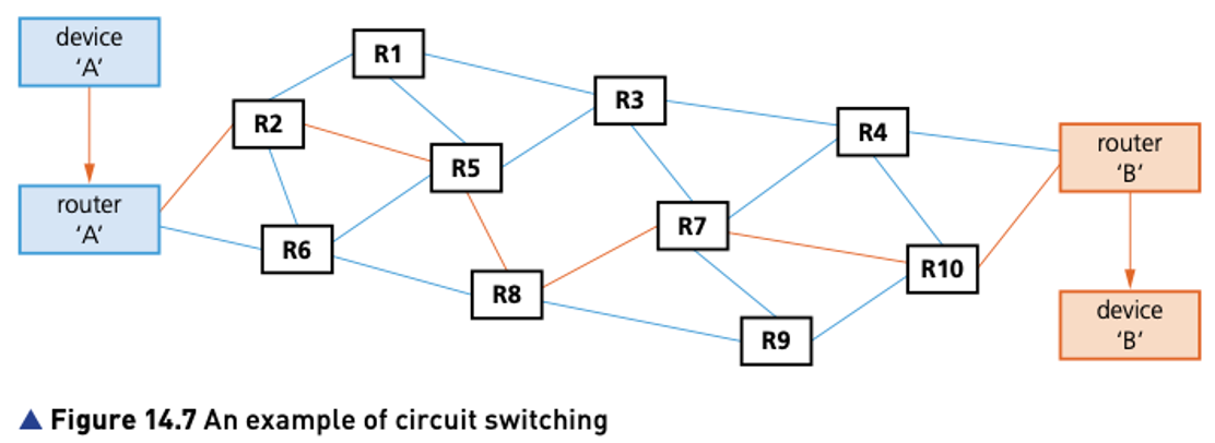
- The dedicated route from ‘A’ to ‘B’ is first of all established (shown in orange on the diagram).
- The following connections are then partially implemented: A–R2, R2–R5, R5–R8, R8–R7, R7–R10 and finally R10–B.
- All packets (frames) follow this single route and communication will take place, provided ‘B’ is not busy.
- The main uses of circuit switching include public telephone networks, private telephone networks and private data networks.

Packet switching
Packet switching was introduced in Chapter 2 when describing VoIP, together with a diagram to show how the individual packets are routed from client to client.
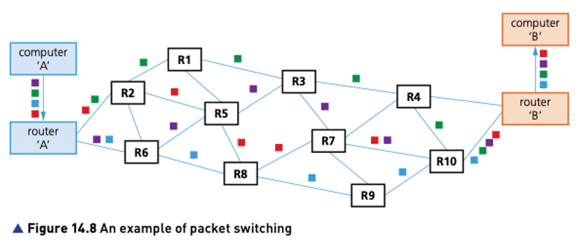
Packet switching is a method of transmission in which a message is broken up into a number of packets that can be sent independently to each other from start point to end point.
The data packets will need to be reassembled into their correct order at the destination.
- each packet follows its own path
- routing selection depends on the number of datagram packets waiting to be processed at each node (router)
- the shortest path available is selected
- packets can reach the destination in a different order to that in which they are sent
As figure shows, the message sent by computer ‘A’ was split into four packets.
The original packet order was:
and they arrived in the order:
which means they need to be reassembled in the correct order at the destination.

| Pros | Cons |
|---|---|
| no need to tie up a communication line | the protocols for packet switching can be more complex than those for circuit switching |
| it is possible to overcome failed or faulty lines by simply re-routing packages | if a packet is lost, the sender must re-send the packet (which wastes time) |
| it is easy to expand the traffic usage | does not work well with real-time data streams |
| circuit switching charges the user on the distance and duration of a connection, but packet switching charges users only for the duration of the connectivity | the circuit/channel has to share its bandwidth with other packets |
| high data transmission is possible with packet switching | there is a delay at the destination while packets are reassembled |
| packet switching always uses digital networks which means digital data is transmitted directly to the destination | needs large amounts of RAM to handle the large amounts of data |
Comparison of circuit switching and packet switching
| Feature | circuit switching | packet switching |
|---|---|---|
| actual route used needs to be set up before transmission can begin | Yes | No |
| a dedicated transmission path is required | Yes | No |
| each packet uses the same route | Yes | No |
| packets arrive at destination in the correct order | Yes | No |
| all the bandwidth of the channel is required | Yes | No |
| is bandwidth wasted? | Yes | No |
Hop number/Hopping
Sometimes it is possible for packets to get lost and keep ‘bouncing’ around from router to router and never actually get to their destination. Eventually, the network could grind to a halt as the number of ‘lost’ packets mounts up and clogs up the system. To overcome this, a method called hopping is used.
A hop number is added to the header of each packet.
Each packet is only allowed to hop a finite number of times (this number is determined by the network protocol and routing table being used).
Each time a packet passes through a router, the hop number is decreased by 1.
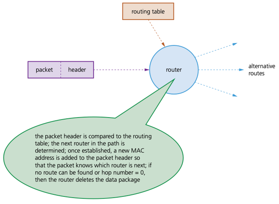
If the packet has not reached its destination and the hop number = 0, then it will be deleted when it reaches the next router.
Routing tables
- Routing tables contain the information necessary to forward a package along the shortest/best route to allow it to reach its destination.
- As soon as the packet reaches a router, the packet header is examined and compared with the routing table.
- The table supplies the router with instructions to send the packet (hop) to the next available router.

Routing tables include
- number of hops
- MAC address of the next router where the packet is to be forwarded to (hopped)
- metrics (a cost is assigned to each available route so that the most efficient route/path is found)
- network destination (network ID) or pathway
- gateway (the same information as the next hop; it points to the gateway through which target network can be reached)
- netmask (used to generate network ID)
- interface (indicates which locally available interface is responsible for reaching the gateway).